Ham Radio EMCOMM Go Kit
by highonsolder
Last year I put together both VHF/UHF and HF go kits. While functional, neither of these was as capable or robust as I ultimately wanted my go kit to be. My new goal was to build an all-in-one station in a box that was not overly bulky or heavy.
Design
 If you look around the internet you will see a lot of people building go kits in rack cases. I always liked the sturdiness and modularity of this type of case, but not the bulk. Most builders us a full size 6 unit case, which is not compact (roughly 24″ square and 13″ tall) nor lightweight (over 18lbs). After evaluating the equipment I planned to use in the kit I realized that I did not need a full depth case. Using a shallow case saves me 8″ of depth and cuts the weight as well. I laid out several possible equipment arrangements in CAD and found that if I kept the kit fairly barebones (no SWR meters or external antenna tuners, only one external speaker) I could also move from a 6 unit case to a 4 unit and still fit everything I needed. The 4 unit shallow case I used is 22.4″ x 16.2″ x 9.1″ and weighs 12.8lbs.
 The general design philosophy for this project was to have all of the equipment mounted to two shelves (one on the bottom and one at the top). After my experiments in CAD I found that a good organizational layout was achieved with the power supply, power distribution, and HF transceiver mounted on the bottom. As part of the power distribution system I wanted to incorporate an automatic backup power switch. This allows the power system to seamlessly change from AC wall/generator power to battery power. While not necessary, this is a nice feature to have because it prevents your radio from turning off while operating if there is an interruption of power (which can easily happen in emergency and field operations).
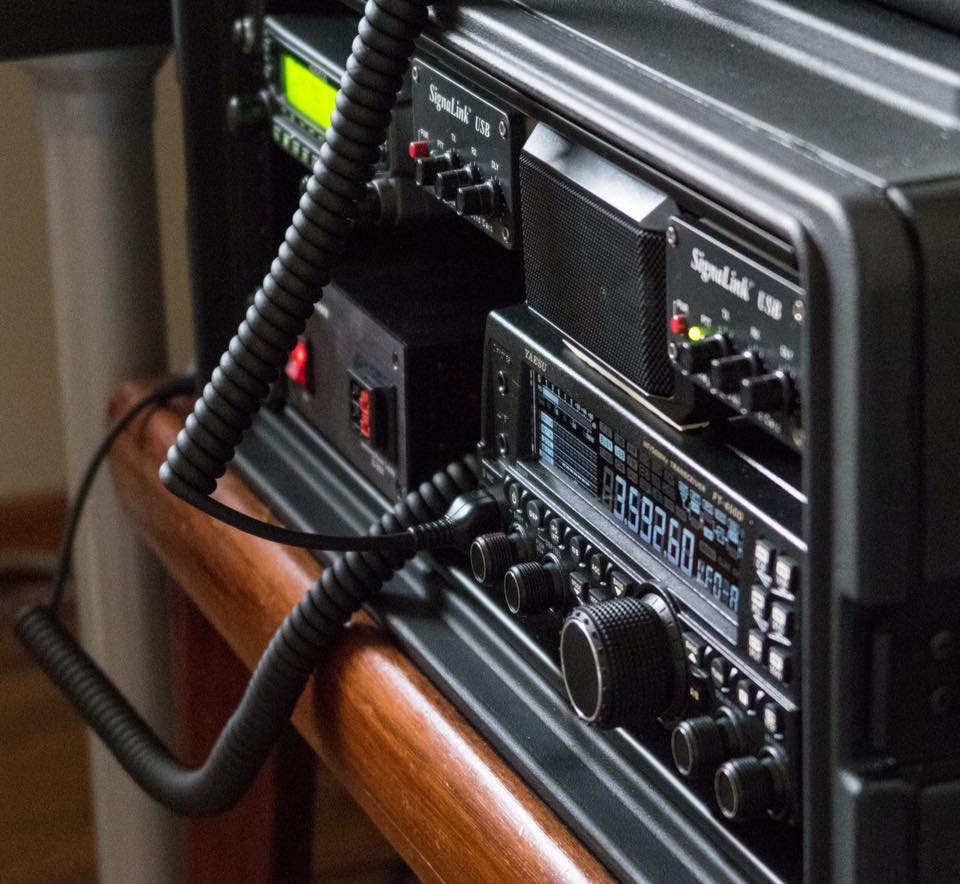
This left the VHF/UHF transceiver, speaker, and two SignaLinks for the top shelf. The SignaLinks are separated by the speaker to easily differentiate which unit is connected to which radio. I went with multiple digital interfaces because while I will most likely never be transmitting on both V/U and HF simultaneously, it can be very handy to be able to monitor both at the same time or to monitor one while transmitting on the other. Having two units also allows me to never worry about changing radio and SignaLink wiring to operate on the band I need to.
 In order to simplify the cabling between the SignaLinks and my laptop I decided to us a powered USB hub and to make the USB hub accessible on the back of the case. This makes it very convenient when in the field since I don’t have to reach into the case to plug in the interface cables. The addition of a rear mounting plate gave me a place to pull out the V/U transceiver’s antenna connection for easier access as well.
I decided one external speaker would be adequate based on the layout I settled on. In this layout there is a fair amount of space below the V/U radio’s speaker to allow for sufficient sound output. The HF radio, however, has much less space above its top mounted speaker. Another consideration I made was that FM audio on V/U is generally very clean, especially compared to SSB audio on HF. Based on this I chose to use the speaker with the HF radio.
Parts
Construction

 The Powerwerx power supply is perfect for go kits. It is very compact (6″ x 5″ x 2″), has convenient Anderson powerpole connections on the front (in addition to terminals on the back), and can be secured with mounting brackets.
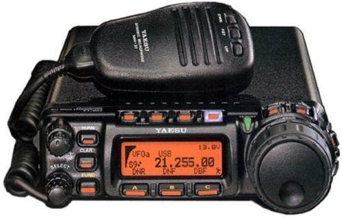
The Yaesu 450D offers a lot of bang-for-your-buck and is relatively compact and lightweight as well (9lbs). The built-in automatic antenna tuner does not have the widest range (3:1), but I don’t plan to use it with non-resonant antennas so it should be more than adequate. Making use of the internal tuner also allowed me to eliminate an external tuner from the design, which was one of the key reasons I was able to fit everything inside a 4 unit case. The 450D was mounted using 2.5″ steel brackets along with M4 machine screws and 1/8″ nylon spacers to prevent the brackets from rubbing against the radio’s enclosure. I had originally intended to use Yaesu’s mobile mount for the 450D, however, it took up too much space and would have affected my layout. This arrangement lifts the radio about 1/2″ off of the shelf which should provide plenty of ventilation.
 In the preliminary layouts I had planned to use a West Mountain Radio PWRgate and Rigrunner for backup power switching and power distribution. This plan proved impractical due to space restrictions, however, I found the perfect substitution in the Low Loss PWRgate. It is about half the size of the other backup power switch and it provides 3 output powerpoles which eliminates the need for a Rigrunner or other distribution block. While the LLPG is rated for 25 amps vs the 40 amps of the other unit, this should still be adequate for my purposes. The LLPG is very lightweight and was mounted using heavy duty double stick tape.

 The Kenwood V71A was mounted using it’s mobile mounting bracket. The voltage converter for the USB hub was screwed to the shelf using its mounting tabs. The other equipment on the upper
  shelf was mounted using either heavy duty velcro (SignaLinks, USB hub) or double stick tape (speaker). I also added some rubber strips to the bottom of the speaker because I found in test fittings that the clearance between the speaker and the HF radio was only about 1/8″ and I didn’t want any inadvertent contact between them when the case is moved.
Cable Management

 Part of eliminating the Rigrunner from my build meant that I had to provide some protection for the power wiring and radios. This was done using inline fuse holders with ATC style fuses. I also had a fair amount of radio interface and USB cables to manage. The shelves I chose are vented which makes them perfect for using wire ties to secure everything in place. I also wanted to make the go kit as straightforward as possible to assemble and disassemble. Part of this goal was limiting the wire tying of cables to individual shelves. This means that if I want to remove a shelf, I only need to disconnect the handful of cables that are connected between the two shelves (two power, one speaker audio, one SignaLink), then unscrew the shelf and pull it out. No cutting of wire ties is necessary.

 I really wanted to be able to stow the radio microphones inside the go kit and I found that I could velcro the V/U radio’s mic to one of the HF radio’s mounting brackets and the microphone’s cable would then fit nicely between the power supply and HF radio. This is especially convenient since the microphone jack is in a position that makes disconnecting it a bit of a pain.

 The HF radio’s mic is stowed using velcro and a strap to the inside of the front case lid. The lid has enough depth that the mic can fit without contacting the front of the power supply. The power supply AC power cord is stowed using a similar strap method as the HF mic, except it is in the rear case lid.
Weight
Part of the goal of using a smaller rack case was to cut down on weight as well as bulk. I had estimated that I could build the go kit and keep the weight around 35lbs. In the end the kit weighs 40.5lbs. I think the lesson I took from this is that wire and mounting hardware add up to more weight than you might realize.
Operation

 The kit is very straightforward to setup. Once the lids are off I simply unstrap the microphones and power cord. Then I can either plug in AC power or a battery, hook up my antennas, connect USB to my laptop, and I’m on the air. I am very happy with how little bulk this kit has; with the lids removed the case is only 12″ deep and easily fits on a small table. The kit is small enough to integrate perfectly into my home station, which makes it very convenient to make sure everything is fully functional for field operations. I am very pleased with how this kit turned out and I learned a lot of along the way, especially about case layout and parts fitment.
Update – Microphone Connector (February 2017)

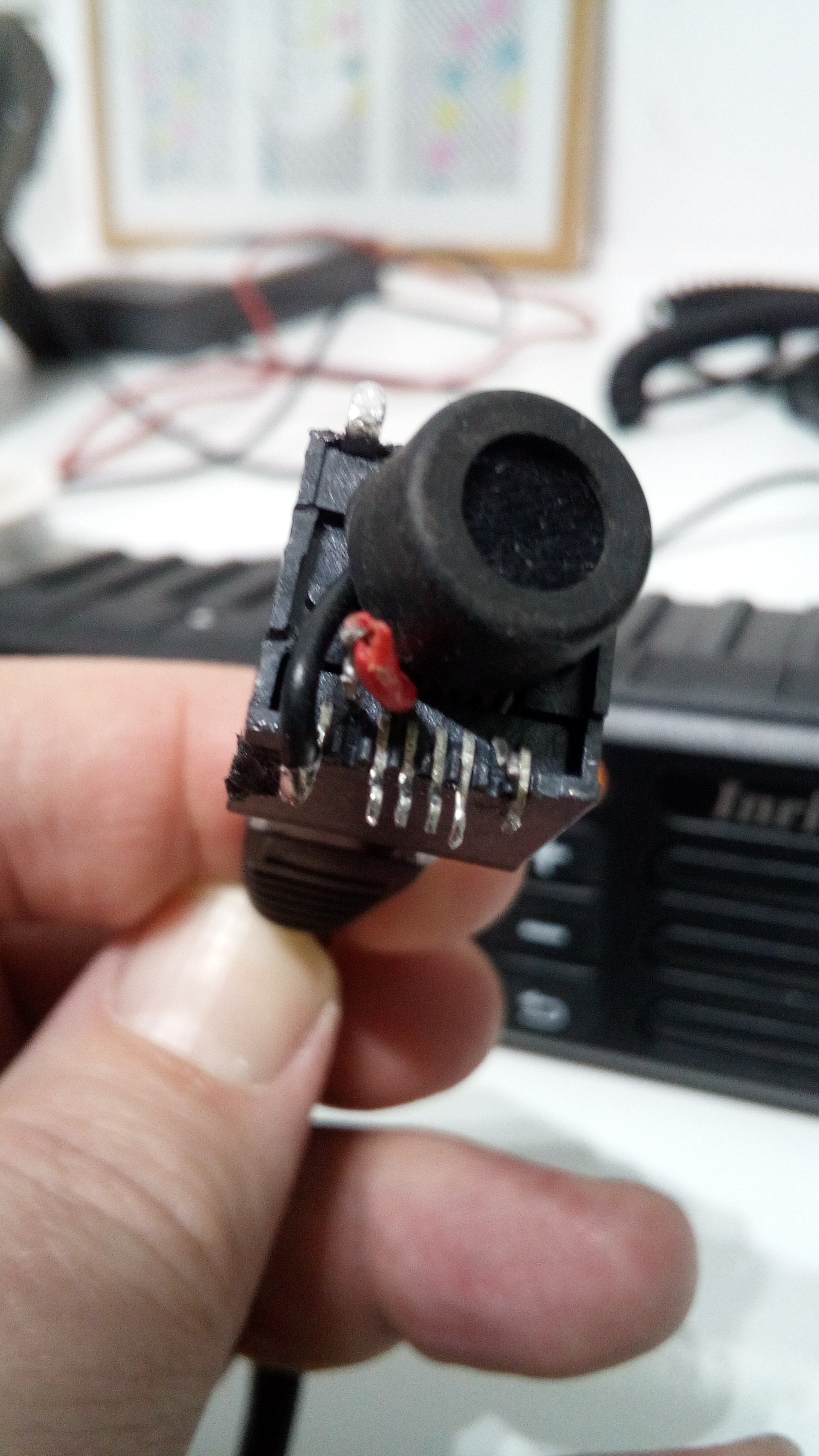
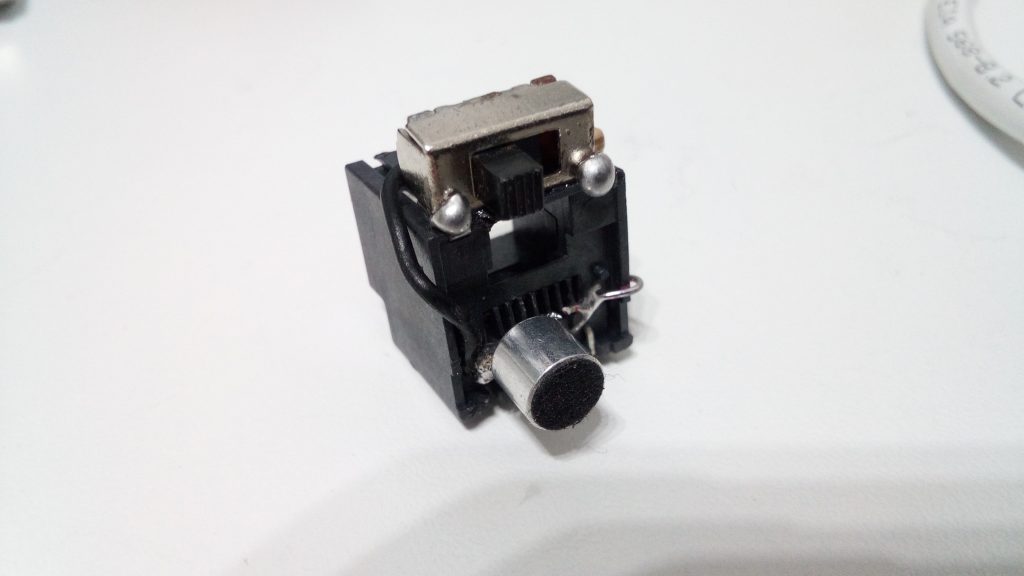
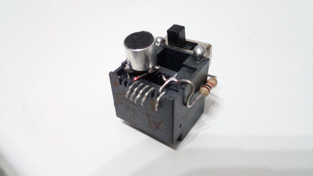
 After using my Go Kit for a few weeks I realized that the Kenwood V71’s microphone connector was not in the best location. It is on the side of the radio and when the mic is being used it twists and otherwise stresses the microphone’s connector. To improve this situation I decided to extend the radio’s mic connection to the front of the Go Kit. I accomplished this using a 1 foot ethernet patch cable and a RJ45 Inline Coupler. The coupler was mounted on the top of the power supply with heavy duty double stick tape. This new arrangement makes the microphone connection much more accessible and greatly reduces the stress on the connectors.
Update – Integration with New Power Box (November 2017)

 Part of building my new Power Box involved modifying the power circuitry for my go kit. Because the battery switching components are now off board I no longer needed the Low Loss PWRgate. In its place
  I installed a Powerwerx PD-4 distribution block. I also used a powerpole mounting clamp and a piece of ABS plastic to create a mount for the output of my power supply. This gives me two solid points of connection from which I can wire to my power box. Or if I am running exclusively off of the power supply I can use a simple jumper for self contained operation.


 Worldwide fast deliveries